Member View Defaults
- General Overview
- Related Tools
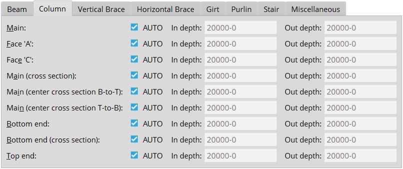
Member Type : Lets you to select the tab for the member you want to adjust the default view depths for.
Preset Views : The preset views that can be assigned to members of a particular type are listed. These views can be assigned automatically, or assigned by users in member isolation. When the member is detailed, all preset views that are assigned to the member (in member isolation) will be shown on the detail.
If this box is checked (
Auto), the Creating 3D material phase of Process and Create Solids calculates the " In depth " and " Out depth " values for that particular preset view. These values are calculated based on the member type, the view type and the main material type.
If this box is not checked (
Auto) the user will enter the specific " In depth " and " Out depth " values.
In/Out depth: " In depth " is the distance in from the plane of the view. " Out depth " is the distance out from the plane of the view.
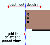
A left end preset view shown as a grid line. The view looks toward the beam. This screen shot was taken from the MAIN VIEW in member isolation .


|
|
OK (or the Enter key) closes this screen and applies the settings.
Cancel (or the Esc key) closes this screen without saving any changes.
Reset undoes all changes made to this screen since you first opened it. The screen remains open.
- Depth check controls (to change view depth in member isolation)
- Member isolation (where view depth can be changed on a case-by-case basis)
- System- and user-created views (both are affected by the settings on this window)
- Detail Members (applies view depth changes to details that incorporate the view)
- Material View Defaults (setup window for isolation of materials -- not members)

